January 21, 2025, 8 min read, by Vinicius Bastos
How to Size Dimmers and Relays Correctly
Learn how to size dimmers and relays correctly: power factor, leading and trailing edge dimming, protection, and sample calculations for LEDs and motors.
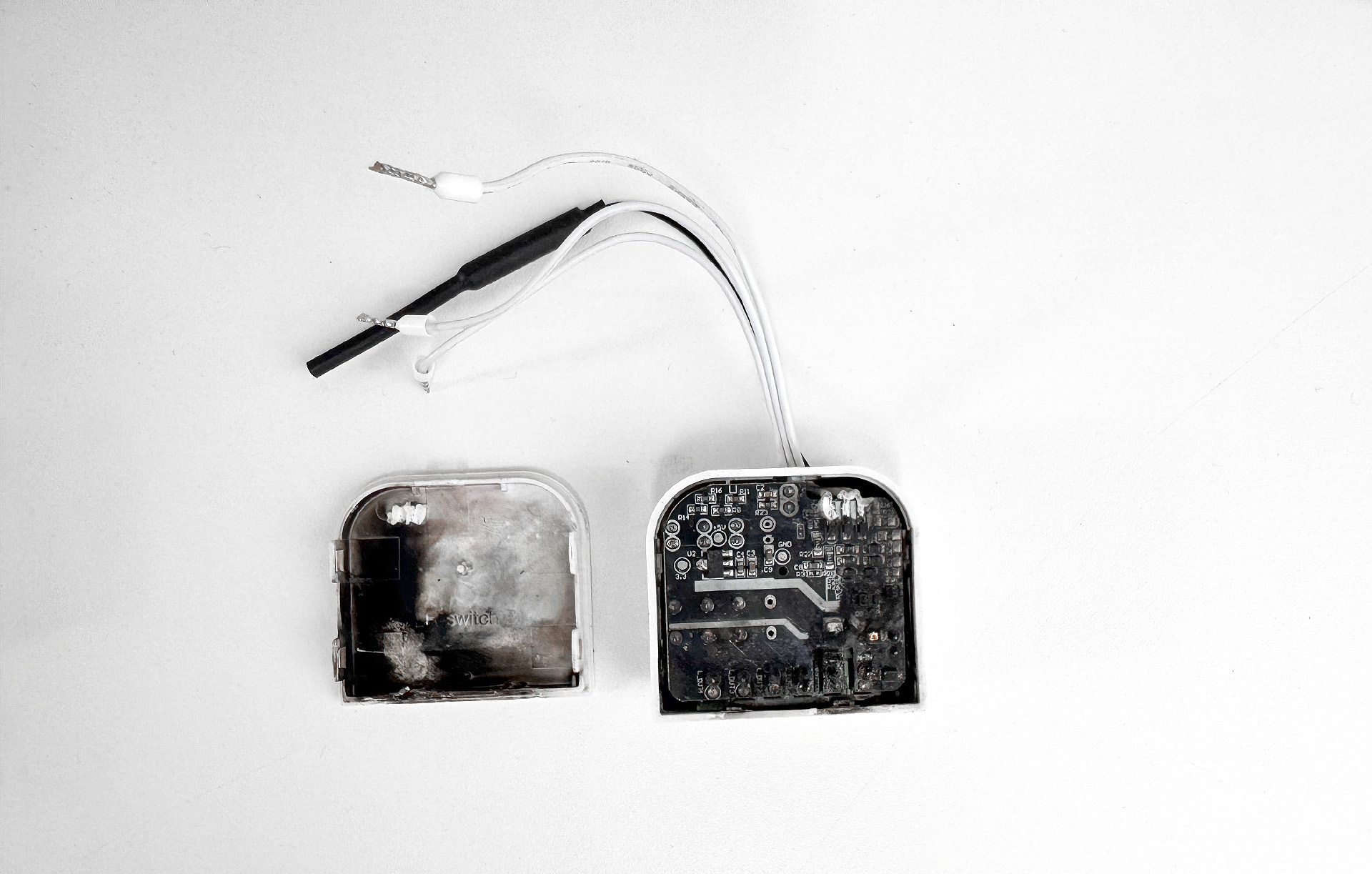
Power factor is a crucial concept that directly affects how home automation devices work.
In this article, you'll learn how different electrical loads affect the performance of relays and dimmers, how this impacts your automation project, and, finally, how to size them correctly.
Understanding power factor
Power factor is a measure of how efficiently electrical energy is used in a circuit.
It's the ratio between active power (which does work) and apparent power (the total supplied by the source).
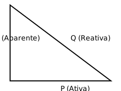
In an ideal circuit, the power factor equals 1: all the energy supplied is converted into useful work.
But in practice, different types of loads can reduce this value:
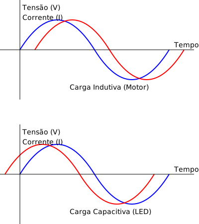
Inductive loads
Current lags behind voltage
Produce a lagging (inductive) power factor
Examples: motors in general, fans, washing machines, air conditioners
Capacitive loads
Current leads voltage
Produce a leading (capacitive) power factor
Examples: switching power supplies, LEDs, computers
Impact on automation devices
This applies to both smart switches and automation modules (see the differences in smart switch or automation module): inside, both use relays and dimmers.
Effects on relays
1. Inrush current
Inductive loads, and LED power supplies too (because of their input capacitors), generate current spikes when they are switched on
They can shorten the life of the relay contacts
They can cause the contacts to weld
2. Electric arcing
Switching off inductive loads produces electric arcs
Premature contact wear
Possible failure to switch off
Effects on dimmers and how the TRIAC works
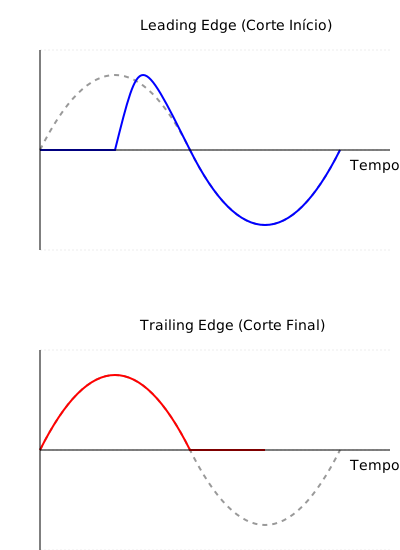
The TRIAC (Triode for Alternating Current) is the main component of traditional dimmers, responsible for controlling the power delivered to the load by chopping the sine wave. Once triggered, it only stops conducting when the current drops to zero, at the end of each half cycle.
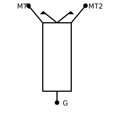
There are two main control methods:
1. Leading Edge (cuts the start of the wave)
The TRIAC stays off at the start of the half cycle
It's triggered at a specific point on the wave and conducts until the end of the half cycle
Traditional method, used in dimmers for resistive and inductive loads
Can cause audible noise with some loads
2. Trailing Edge (cuts the end of the wave)
The load is switched on at the start of the half cycle
It's switched off before the end of the half cycle
Since the TRIAC can't turn off in the middle of the half cycle, this cut is made by transistors (MOSFET or IGBT), which is why these dimmers usually need the neutral wire
Better suited to capacitive loads (LEDs and switching power supplies)
Produces less electromagnetic interference
Problems caused by low power factor
1. TRIAC overload
Loads with a low power factor create a phase shift between voltage and current
The TRIAC may not turn off properly at the zero crossing
This results in excessive heating and possible component failure
2. Effects on the loads
Flicker in LEDs
Unstable brightness control
Possible damage to LED drivers
3. Electromagnetic interference
Electrical noise
Possible interference with nearby equipment
Dimming solutions
1. Choosing the right type of dimmer
Leading Edge for resistive and inductive loads
Trailing Edge for LEDs and electronic loads
Check compatibility with the load
2. Required protection
Snubber circuits to protect the TRIAC
EMI filters to reduce interference
Thermal protection
3. Sizing
Take the load's power factor into account
Include a safety margin in the calculation (we'll see how below)
Check the load's inrush current
Best practices
For relays
1. Sizing
Use relays rated above the load
Factor the inrush current into the calculation
Use surge suppressors when needed
2. Protection
Install an RC filter for inductive loads
Use varistors for surge protection
Separate circuits
For dimmers
1. Choosing correctly
Use dimmers designed for LED
Check compatibility with the bulbs
Avoid dimmable power supplies and choose AC 100/240V LEDs (for LED strips, dedicated controllers are best)
Check the maximum LED wattage on the spec sheet, which is usually much lower than the rating for incandescent or halogen bulbs (on one American Lutron model, for example, it's 150W for LED versus 600W for incandescent)
2. Installation
Respect the minimum and maximum load: below the minimum load, the current may not reach the minimum needed to keep the TRIAC conducting, and the LED flickers
Use suitable conductors
Calculate the circuit's power taking the power factor into account
Sizing examples
Example 1: dimmer for LED lighting
Consider an installation with:
10 LED bulbs of 12W each (120W total)
Typical LED power factor: 0.6
Line voltage: 220V
In practice, use the power factor the manufacturer lists on the bulb's packaging or spec sheet: it varies from one model to another.
Calculations:
1. Apparent power (S = P/PF)
S = 120W / 0.6 = 200VA
2. Actual current (I = S/V)
I = 200VA / 220V = 0.91A
3. Sizing the dimmer
Minimum rated current of the dimmer: 0.91A × 1.8 (safety factor) = 1.64A
Recommendation: use a dimmer rated 2A or higher
It must be a Trailing Edge type for LEDs
Important: in this case, even with only 120W of load, we need a dimmer sized for 200VA because of the low power factor and, with the safety margin, for about 360VA (1.64A × 220V).
Example 2: relay for a fan motor
Consider:
200W fan motor
Power factor: 0.8 (inductive)
Voltage: 220V
Starting current: 6 × rated current
Calculations:
1. Apparent power
S = 200W / 0.8 = 250VA
2. Rated current
I = 250VA / 220V = 1.14A
3. Starting current
I_start = 1.14A × 6 = 6.84A
4. Sizing the relay
Minimum contact current: 6.84A × 1.5 (safety factor) = 10.26A
Recommendation: use a 16A relay with an RC filter in parallel
Example 3: dimmer with mixed loads
Scenario:
5 dimmable 7W LED spotlights (35W total, PF = 0.6)
2 halogen bulbs of 50W (100W total, PF = 1.0)
Voltage: 220V
Calculations:
1. Apparent power of the LEDs
S_LED = 35W / 0.6 = 58.33VA
2. Apparent power of the halogens
S_HAL = 100W / 1.0 = 100VA
3. Total apparent power
S_TOTAL = 58.33VA + 100VA = 158.33VA (the direct sum comes out slightly above the actual value, which works in favor of safety)
4. Total current
I = 158.33VA / 220V = 0.72A
5. Sizing
Minimum dimmer current: 0.72A × 2 = 1.44A
Recommendation: a 2A universal dimmer that supports mixed loads
General recommendations
1. Safety factors
For dimmers with LED: multiply by 1.8 to 2.0
For relays with inductive loads: multiply by 1.5 to 2.0
For mixed loads: use the higher factor
2. Ambient temperature
Derate capacity by 20% in environments above 40°C
Ensure adequate ventilation in the electrical panel
3. Protection
Circuit breaker: size it at 1.3 × rated current, without exceeding the current-carrying capacity of the circuit's cable (under NBR 5410, the breaker's rated current falls between the design current and the cable's capacity, because its main job is to protect the conductor)
RC filter: required for inductive loads
SPD: recommended for overall protection
4. Installation
Use a 4×4 box or larger for dimmers
Keep a minimum distance between power devices
Plan for adequate heat dissipation
Recommendations for projects
1. Load analysis
Identify the types of loads on the circuit
Calculate the total power factor
Anticipate possible problems
2. Specification
Choose compatible devices
Size with a safety margin
Consider future expansions
3. Preventive maintenance
Monitor device temperature
Check for signs of wear
Take periodic measurements
Conclusion
Understanding power factor and its impact on home automation devices is essential to ensure safe installations.
As we saw in the examples, correct sizing goes far beyond simply considering the rated power of the loads.
The way dimmers work illustrates this complexity: a seemingly simple component needs to be carefully specified, taking into account not only the power but also the type of load, the control method (Leading or Trailing Edge), and the circuit's power factor.
The wrong choice can lead to anything from malfunctions to burned-out devices.
The calculations show that a low power factor can require significant oversizing of devices: in example 1, the 120W load called for a dimmer rated for about 360VA, three times the rated power.
This aspect is often overlooked in projects, resulting in failures and dissatisfied customers.
Home automation requires a well-grounded approach from the professional. It's not enough to simply install devices; you need to:
Understand the nature of the loads being controlled
Correctly calculate the actual currents, taking the power factor into account
Specify devices suited to the type of load
Implement the necessary protection
Ensure an installation that allows proper heat dissipation
By following these guidelines and applying the concepts and calculations presented, professionals will be able to develop robust and reliable home automation projects, avoiding common problems such as burned-out components, unwanted interference, and erratic operation of control devices.